- ARDUINO CAMERA ETHERNET MOVIE
- ARDUINO CAMERA ETHERNET FULL
- ARDUINO CAMERA ETHERNET SOFTWARE
- ARDUINO CAMERA ETHERNET CODE
- ARDUINO CAMERA ETHERNET SERIES
By resetting the read pointer to the beginning of the image data, user can read the same image data from the start point again. Sometimes user wants to read the same frame of image data multiple times for processing, the rewind read operation is designed for this purpose. It is recommended to use burst read operation to get better throughput performance. While burst read operation only need to send a read command then read multiple image data in one SPI read operation cycle.

Normal read operation reads each image data by sending a read command in one SPI read operation cycle. With proper register settings to the sensor, user can get different resolution with JPEG image stream output. The JPEG compression function is implemented in the image sensor. By setting the maximum number of frames in the corresponding register, the ArduCAM will capture continuous frames until the 8MByte frame buffer is full.
ARDUINO CAMERA ETHERNET MOVIE
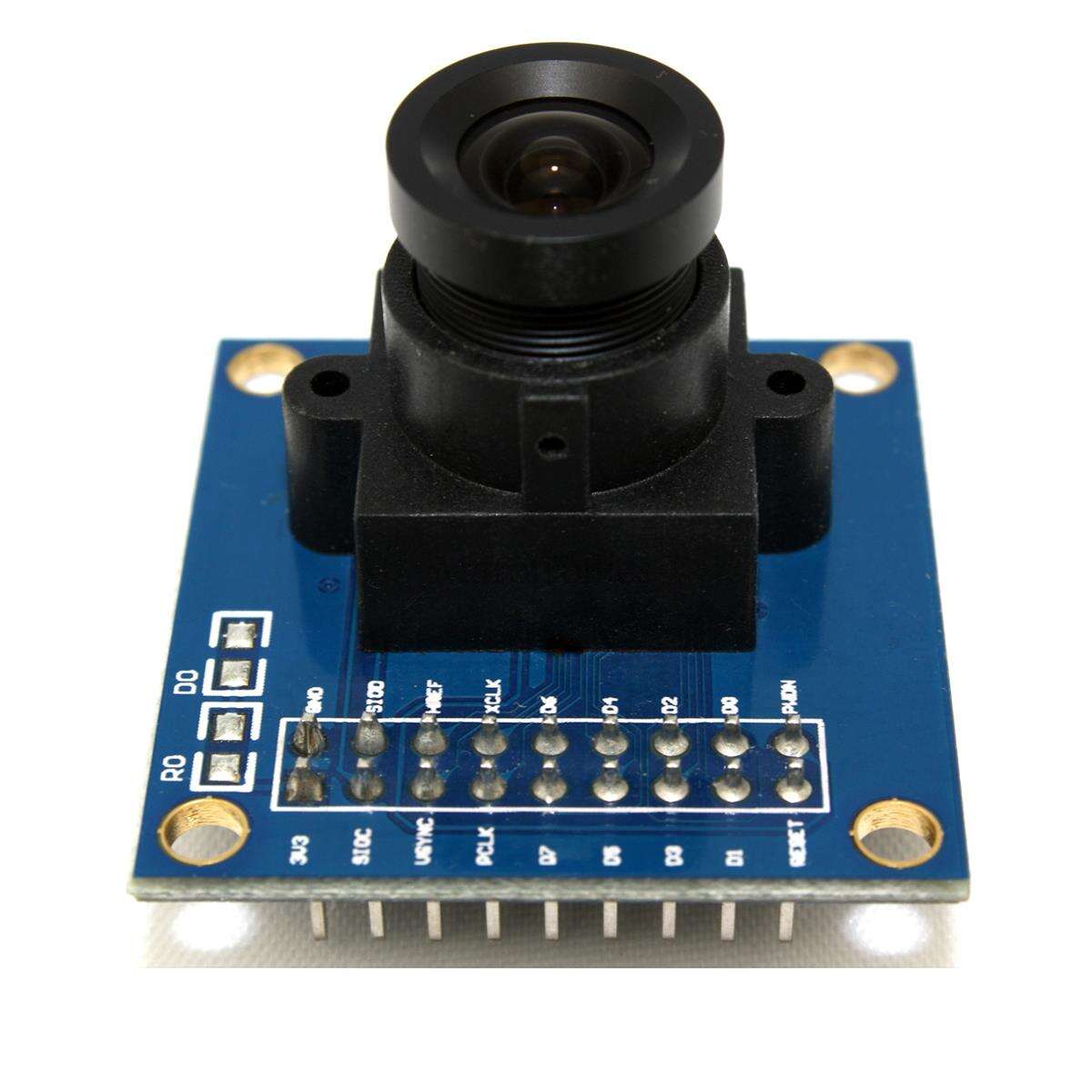
Short movie recording mode is advanced capture mode. By setting the number of frames in the capture register, the ArduCAM will capture consequent frames after issuing capture command. Multiple capture mode is advanced capture mode. User only needs to poll the flag bit from the register to check out if the capture is done. After issuing a capture command via SPI port, the ArduCAM will wait for a new frame and buffer the one entire image data to the frame buffer, and then assert the completion flag bit in the register. Single capture mode is the default capture mode of the camera. The ArduChip uses ArduCAM proprietary third generation camera controller technology which handles the complex camera, memory, LCD and user interface hardware timing and provides a user friendly SPI interface. Table 5 Camera Interface Pin Definition PINįigure 3 shows the block diagram of ArduCAM shield which is composed by the camera module, LCD screen and an ArduChip. Table 4 Alternative P6 Pin Definition PIN Table 3 ArduCAM Shield V2 Pin Definition PIN NAME The forth connector U5 is for ArduCAM Nano ESP8266 module extension, the pin definition see Table 6. The third connector is for camera module, the pin definition see Table 5. The second connector P6 is an alternative port for Arduino pins, some of them are used by ArduCAM shield, the others are free pins, the pin definition see Table 4. One is standard ArduCAM connector which can well mate with Arduino board, the pin definition see Table 3. There are four connectors on ArduCAM shield. Key Specifications Power supply 5V/50mAįigure 2 shows the pin out diagram for ArduCAM shield V2. Table 2 Tested Hardware Platforms Platformģ. Table 1 Supported Camera Modules Resolution Well mated with standard Arduino boards.All ArduCAM’s IO ports are 5V/3.3V tolerant .

ARDUINO CAMERA ETHERNET CODE


Support almost any microcontroller platform, see Table 2
ARDUINO CAMERA ETHERNET FULL
It can not only capture decent 5MP JPEG images, but also can do 5MP full resolution RAW image capture, which makes it to be the ideal solution for IoT and scientific image processing applications. The ArduCAM supports variety camera modules from 0.3MP to 5MP with different format like RAW, RGB, YUV, JPEG and can be well mated with standard Arduino boards.ĪrduCAM V2 is the second generation of ArduCAM shields, it offers the improved performance and enhanced functions than the previous revisions. User can make it works in minutes without writing a line of code.
ARDUINO CAMERA ETHERNET SOFTWARE
It hides the complex nature of the camera and provides the plug and play camera control interface as well as the ready to use software source code library and demo code.
ARDUINO CAMERA ETHERNET SERIES
ArduCAM series camera shield is a universal camera control board for Arduino.


 0 kommentar(er)
